Sunday, 23 June 2013
Tuesday, 18 June 2013
Unit 66 - Constraints
Constraints
What constraints are involved in working within a 3D environment - polygon count, file size and rendering time?
Rendering Time
Polygon Count and File Size
The two common measurements of an object's 'cost’ or file size are the polygon count and vertex count. For example, a game character may stretch anywhere from 200-300 polygons, to 40,000+ polygons. A high-end third-person console or PC game may use many vertices or polygons per character, and an iOS tower defence game might use very few per character.
Polygons Vs. Triangles
When a game artist talks about the poly count of a model, they really mean the triangle count. Games almost always use triangles not polygons because most modern graphic hardware is built to accelerate the rendering of triangles.
The polygon count that's reported in a modelling app is always misleading, because a model's triangle count is higher. It's usually best therefore to switch the polygon counter to a triangle counter in your modelling app, so you're using the same counting method everyone else is using.
Polygons however do have a useful purpose in game development. A model made of mostly four-sided polygons (quads) will work well with edge-loop selection & transform methods that speed up modelling, make it easier to judge the "flow" of a model, and make it easier to weight a skinned model to its bones. Artists usually preserve these polygons in their models as long as possible. When a model is exported to a game engine, the polygons are all converted into triangles automatically. However different tools will create different triangle layouts within those polygons. A quad can end up either as a "ridge" or as a "valley" depending on how it's triangulated. Artists need to carefully examine a new model in the game engine to see if the triangle edges are turned the way they wish. If not, specific polygons can then be triangulated manually.
Triangle Count vs. Vertex Count
Vertex count is ultimately more important for performance and memory than the triangle count, but for historical reasons artists more commonly use triangle count as a performance measurement. On the most basic level, the triangle count and the vertex count can be similar if the all the triangles are connected to one another. 1 triangle uses 3 vertices, 2 triangles use 4 vertices, 3 triangles use 5 vertices, and 4 triangles use 6 vertices and so on. However, seams in UVs, changes to shading/smoothing groups, and material changes from triangle to triangle etc. are all treated as a physical break in the model's surface, when the model is rendered by the game. The vertices must be duplicated at these breaks, so the model can be sent in renderable chunks to the graphics card.
Overuse of smoothing groups, over-splittage of UVs, too many material assignments (and too much misalignment of these three properties), all of these lead to a much larger vertex count. This can stress the transform stages for the model, slowing performance. It can also increase the memory cost for the mesh because there are more vertices to send and store.
Rendering Time
Rendering is the final process of creating the actual 2D image or animation from the prepared scene. This can be compared to taking a photo or filming the scene after the setup is finished in real life. Several different, and often specialised, rendering methods have been developed. These range from the distinctly non-realistic wireframe rendering through polygon-based rendering, to more advanced techniques such as: scanline rendering, ray tracing, or radiosity. Rendering may take from fractions of a second to days for a single image/frame. In general, different methods are better suited for either photo-realistic rendering, or real-time rendering.
Real-time
Rendering for interactive media, such as games and simulations, is calculated and displayed in real time, at rates of approximately 20 to 120 frames per second. In real-time rendering, the goal is to show as much information as possible as the eye can process in a fraction of a second, i.e. one frame. The primary goal is to achieve an as high as possible degree of photorealism at an acceptable minimum rendering speed (usually 24 frames per second, as that is the minimum the human eye needs to see to successfully create the illusion of movement). In fact, exploitations can be applied in the way the eye 'perceives' the world, and as a result the final image presented is not necessarily that of the real-world, but one close enough for the human eye to tolerate. Rendering software may simulate such visual effects as lens flares, depth of field or motion blur. These are attempts to simulate visual phenomena resulting from the optical characteristics of cameras and of the human eye. These effects can lend an element of realism to a scene, even if the effect is merely a simulated artefact of a camera. This is the basic method employed in games, interactive worlds and VRML. The rapid increase in computer processing power has allowed a progressively higher degree of realism even for real-time rendering, including techniques such as HDR rendering. Real-time rendering is often polygonal and aided by the computer's GPU.
Non Real-time
Animations for non-interactive media, such as feature films and video, are rendered much more slowly. Non-real time rendering enables the leveraging of limited processing power in order to obtain higher image quality. Rendering times for individual frames may vary from a few seconds to several days for complex scenes. Rendered frames are stored on a hard disk then can be transferred to other media such as motion picture film or optical disk. These frames are then displayed sequentially at high frame rates, typically 24, 25, or 30 frames per second, to achieve the illusion of movement.
When the goal is photo-realism, techniques such as ray tracing or radiosity are employed. This is the basic method employed in digital media and artistic works. Techniques have been developed for the purpose of simulating other naturally-occurring effects, such as the interaction of light with various forms of matter. Examples of such techniques include particle systems (which can simulate rain, smoke, or fire), volumetric sampling (to simulate fog, dust and other spatial atmospheric effects), caustics (to simulate light focusing by uneven light-refracting surfaces, such as the light ripples seen on the bottom of a swimming pool), and subsurface scattering (to simulate light reflecting inside the volumes of solid objects such as human skin).
The rendering process is computationally expensive, given the complex variety of physical processes being simulated. Computer processing power has increased rapidly over the years, allowing for a progressively higher degree of realistic rendering. Film studios that produce computer-generated animations typically make use of a render farm to generate images in a timely manner. However, falling hardware costs mean that it is entirely possible to create small amounts of 3D animation on a home computer system. The output of the renderer is often used as only one small part of a completed motion-picture scene. Many layers of material may be rendered separately and integrated into the final shot using compositing software.
Reflection/Scattering - How light interacts with the surface at a given point
Shading - How material properties vary across the surface
Unit 66 - 3D Development Software
3D Development Software
Examine the software tools used in the production of 3D models.
For example, 3D Studio Max, Maya, LightWave, Cinema 4D, Blender, Sketchup, ZBrush etc.

Maya

LightWave
Blender

Cinema 4D
ZBrush

Sketchup

File Formats
Each 3D application allows the user to save their work, both objects and scenes, in a proprietary file format and export in open formats.
3D Studio Max
Autodesk 3ds Max, formerly 3D Studio Max, is 3D computer graphics software for making 3D animations, models, and images. It was developed and produced by Autodesk Media and Entertainment. It has modelling capabilities, a flexible plugin architecture and can be used on the Microsoft Windows platform. It is frequently used by video game developers, TV commercial studios and architectural visualization studios. It is also used for movie effects and movie pre-visualization.
In addition to its modelling and animation tools, the latest version of 3ds Max also features shaders (such as ambient occlusion and subsurface scattering), dynamic simulation, particle systems, radiosity, normal map creation and rendering, global illumination, a customizable user interface, and its own scripting language.
Maya
Autodesk Maya, commonly shortened to Maya, is 3D computer graphics software that runs on Microsoft Windows, Mac OS and Linux, originally developed by Alias Systems Corporation (formerly Alias|Wavefront) and currently owned and developed by Autodesk, Inc. It is used to create interactive 3D applications, including video games, animated film, TV series, or visual effects. The product is named after the Sanskrit word Maya, the Hindu concept of illusion.
Maya 1.0 was released in February 1998. Following a series of acquisitions, Maya was bought by Autodesk in 2005.[8][9] Under the name of the new parent company, Maya was renamed Autodesk Maya. However, the name "Maya" continues to be the dominant name used for the product.
LightWave
LightWave is a software package used for rendering 3D images, both animated and static. It includes a rendering engine that supports such advanced features as realistic reflection and refraction, radiosity, and caustics. The 3D modeling component supports both polygon modeling and subdivision surfaces. The animation component has features such as reverse and forward kinematics for character animation, particle systems and dynamics. Programmers can expand LightWave's capabilities using an included SDK which offers LScript scripting (a proprietary scripting language) and common C language interfaces.

Blender
Blender is a free and open-source 3D computer graphics software product used for creating animated films, visual effects, interactive 3D applications or video games. Blender's features include 3D modeling, UV unwrapping, texturing, rigging and skinning, fluid and smoke simulation, particle simulation, animating, match moving, camera tracking, rendering, video editing and compositing. It also features a built-in game engine.
Cinema 4D
CINEMA 4D is a 3D modeling, animation and rendering application developed by MAXON Computer GmbH of Friedrichsdorf, Germany. It is capable of procedural and polygonal/subd modeling, animating, lighting, texturing, rendering, and common features found in 3d modelling applications.
Four variants are currently available from MAXON: a core CINEMA 4D 'Prime' application, a 'Broadcast' version with additional motion-graphics features, 'Visualize' which adds functions for architectural design and 'Studio', which includes all modules. CINEMA 4D runs on Windows and Macintosh PC's.
Initially, CINEMA 4D was developed for Amiga computers in the early 1990s, and the first three versions of the program were available exclusively for that platform. With v4, however, MAXON began to develop the program for Windows and Macintosh computers as well, citing the wish to reach a wider audience and the growing instability of the Amiga market following Commodore's bankruptcy.
ZBrush
ZBrush is a digital sculpting tool that combines 3D/2.5D modeling, texturing and painting. It uses a proprietary "pixol" technology which stores lighting, colour, material, and depth information for all objects on the screen. The main difference between ZBrush and more traditional modelling packages is that it is more akin to sculpting.
ZBrush is used as a digital sculpting tool to create high-resolution models (up to ten million polygons) for use in movies, games, and animations. It is used by companies ranging from ILM to Electronic Arts. ZBrush uses dynamic levels of resolution to allow sculptors to make global or local changes to their models. ZBrush is most known for being able to sculpt medium to high frequency details that were traditionally painted in bump maps. The resulting mesh details can then be exported as normal maps to be used on a low poly version of that same model. They can also be exported as a displacement map, although in that case the lower poly version generally requires more resolution. Or, once completed, the 3D model can be projected to the background, becoming a 2.5D image (upon which further effects can be applied). Work can then begin on another 3D model which can be used in the same scene. This feature lets users work with extremely complicated scenes without heavy processor overhead.
Sketchup
SketchUp is a 3D modelling program for a broad range of applications such as architectural, civil, mechanical, film as well as video game design — and available in free as well as 'professional' versions.
The program highlights its ease of use,[4] and an online repository of model assemblies (e.g., windows, doors, automobiles, entourage, etc.) known as 3D Warehouse enables designers to locate, download, use and contribute free models. The program includes a drawing layout functionality, allows surface rendering in variable "styles," accommodates third-party "plug-in" programs enabling other capabilities (e.g., near photo realistic rendering) and enables placement of its models within Google Earth.
File Formats
Each 3D application allows the user to save their work, both objects and scenes, in a proprietary file format and export in open formats.
A proprietary format is a file format where the mode of presentation of its data is the intellectual property of an individual or organisation which asserts ownership over the format. In contrast, a free format is a format that is either not recognised as intellectual property, or has had all claimants to its intellectual property release claims of ownership. Proprietary formats can be either open if they are published, or closed, if they are considered trade secrets. In contrast, a free format is never closed.
Proprietary formats are typically controlled by a private person or organization for the benefit of its applications, protected with patents or as trade secrets, and intended to give the license holder exclusive control of the technology to the (current or future) exclusion of others.
Examples of proprietary formats, AutoCAD - .dxf, 3D Studio Max - .3ds, Maya - .mb, LightWave - .lwo
Examples of open formats, .obj and .dae.Unit 66 - Mesh Construction
Mesh Construction
Although it is possible to construct a mesh by manually specifying vertices and faces, it is much more common to build meshes using a variety of tools. A wide variety of 3d graphics software packages are available for use in constructing polygon meshes.
Box modelling
Box modelling is a very popular method which involves the process of starting with a primitive box and manipulating it though various methods. It's basically the process of turning a very simple shape into a very complex one allowing you to construct these meshes though two simple tools. Firstly there is the subdivide tool which spilts faces and edges into smaller pieces by added new vertices and connecting them. If you wanted to subdivivde a square, for example, you could subevide it which would add one vertex in the center and one on each edge, resulting in four smaller squares. Another method includes using the extrude tool; this tool allows you to effectivly drag out/elongate or invert a form from a face or group of faces. It creates a new face of the same size and shape which is connected to each of the existing edges by a face. It's very useful for quickly extending objects. An example of the stages of box moddling is below.
Primitive modelling
A more reserved a less common approch to 3D modelling is the primitive modelling method. This involves creating larger objects by simply combining primitives to create new shapes. The method normally isn't a very effective way to produce complex shapes, and thus is usually only applied to very rigid or simple objects. Some of the primitives could be any of the ones included in the package, which could be things like cubes, pyramids, cylinders, spheres, and 2D primitives like squares, triangles, and disks.
Specialised modelling
The modelling techniques such as box modeling and extrusion modeling are alright for general modelling of objects, but if you need something a bit more organic or detailed, you need more specialised modelling. For this kind of modelling, specialised methods of constructing high or low detailed meshes exist. For example there is sketch based modeling available allowed construction of low detail models very quickly in a user friendly interface, and 3D scanners can be used to make very high detail meshes based on real world objects in a very automtic way. However, these kind of devices are very expensive are thus are usually reserved for researches and industry professionals that really need the high level of accuracy and sub-millimetric digital representations of an object.


(http://www.3dscanco.com/assets/images/products/artec_mht.jpg)
(http://blog.3d3solutions.com/Portals/43940/images/3d_face_scan.jpg)
Info:
http://southerngfx.co.uk/tutorials/box-modelling
http://jessgrafton.wordpress.com/3d/mesh-construction/
http://my.safaribooksonline.com/book/animation-and-3d/9780470102602/working-with-meshes/extrusion_modeling_and_box_modeling
http://en.wikipedia.org/wiki/Polygonal_modeling
http://www.education.vic.gov.au/school/teachers/teachingresources/discipline/maths/assessment/pages/primitivemod.aspx
http://www.peachpit.com/articles/article.aspx?p=30594&seqNum=5
http://en.wikipedia.org/wiki/3D_scanner
Box modelling

Extrusion modelling
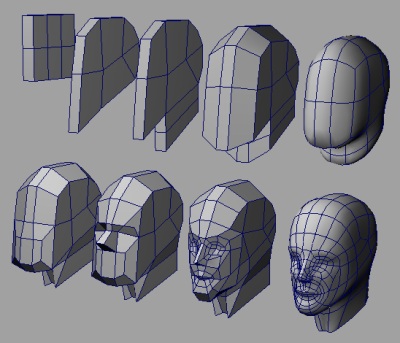
There's another method of 3D modeling usually referred to as extrustion modelling or inflation modeling. Exactly as the name suggests, it involves the process of extending or shortening a polygon from it's origin, whereby a 2D shape is created (often using placed points and connecting them to create a polygon), it is often traced from a photo or drawing. The object is traced from two different angles, in diferent viewports, before the user extrudes the shape into 3D making sure it matched up in both view ports. It's a very popular method of making faces and heads due to the complexity usually involved- it can take a long time, but often produces a much more organic effect. Normally, the artist only models half the object (if it is symettrical) and then duplicates and flips the other half to save time- This is not exclusive to extrusion modelling but is a method often used in this scenario.
Primitive modelling
A more reserved a less common approch to 3D modelling is the primitive modelling method. This involves creating larger objects by simply combining primitives to create new shapes. The method normally isn't a very effective way to produce complex shapes, and thus is usually only applied to very rigid or simple objects. Some of the primitives could be any of the ones included in the package, which could be things like cubes, pyramids, cylinders, spheres, and 2D primitives like squares, triangles, and disks.
Specialised modelling
The modelling techniques such as box modeling and extrusion modeling are alright for general modelling of objects, but if you need something a bit more organic or detailed, you need more specialised modelling. For this kind of modelling, specialised methods of constructing high or low detailed meshes exist. For example there is sketch based modeling available allowed construction of low detail models very quickly in a user friendly interface, and 3D scanners can be used to make very high detail meshes based on real world objects in a very automtic way. However, these kind of devices are very expensive are thus are usually reserved for researches and industry professionals that really need the high level of accuracy and sub-millimetric digital representations of an object.
(http://www.3dscanco.com/assets/images/products/artec_mht.jpg)
(http://blog.3d3solutions.com/Portals/43940/images/3d_face_scan.jpg)
Info:
http://southerngfx.co.uk/tutorials/box-modelling
http://jessgrafton.wordpress.com/3d/mesh-construction/
http://my.safaribooksonline.com/book/animation-and-3d/9780470102602/working-with-meshes/extrusion_modeling_and_box_modeling
http://en.wikipedia.org/wiki/Polygonal_modeling
http://www.education.vic.gov.au/school/teachers/teachingresources/discipline/maths/assessment/pages/primitivemod.aspx
http://www.peachpit.com/articles/article.aspx?p=30594&seqNum=5
http://en.wikipedia.org/wiki/3D_scanner
Unit 66 - Geometric Theory
Geometry
In a 3D workshop, assets are calculated using the same kind of formular as is found in 2D vector art. It's essensially the equivilant of 3D vector, the only difference in algorithm being that there is an extra dimention to be included in the calculations- but the main principles remain the same - Vertices can be scaled, rotated and 'scewed', without any loss of quality like you would find in a bitmap item. This vector style approch is achieved by plotting mathematical points along the axes. This, in turn creates a series of coordinates which are connected to create paths or lines. Because the values of these points are constantly monitered and their values altered as needed, it makes it a very precise and linear art. The shapes created can then easily have polygons created and filled with colour. Becuase it's all mathematical, there is no room for errors, and so if there is even a slight error in the geometry such as a break in the paths, or a double set of points too close to one another, this could make things a lot more difficult. 1+1 doesn't equal 3; however close it is, it doesn't matter. There's only 1 right answer, and everything needs to be correct to continue running smoothing.
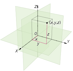
Cartesian Coordinates System
Geometric theory and polygons
Mesh modeling involves, effectivly a 3D space filled with join up coordinates on a grid to make polygons and edges. These coordinates are basic objects, points in the 3D space known as a vertex. Two of these vertices can hence be connected to form and edge, and another vertex makes another edge; forming the most basic polygon you can make; A triangle. This the very basic principle of how points in space can be connected mathmatically to form the most simple of shapes, but joined together, things can get much more complex resulting in vast and intricate 3D forms often make from thousands of vertices, edges and polygons. A well as trianglular polygons, if 4 vertices are connected rather than three, this will make a quad. A face refers to the polygons making up an element (a group of polygons with common vertices).
Mesh modeling involves, effectivly a 3D space filled with join up coordinates on a grid to make polygons and edges. These coordinates are basic objects, points in the 3D space known as a vertex. Two of these vertices can hence be connected to form and edge, and another vertex makes another edge; forming the most basic polygon you can make; A triangle. This the very basic principle of how points in space can be connected mathmatically to form the most simple of shapes, but joined together, things can get much more complex resulting in vast and intricate 3D forms often make from thousands of vertices, edges and polygons. A well as trianglular polygons, if 4 vertices are connected rather than three, this will make a quad. A face refers to the polygons making up an element (a group of polygons with common vertices).
According to Euclidean geometry, any group of three non-collinear points (points not lined up in a straight line) appoint a plane. It's obvious then, that a triangle must always inhabit a single plane as the three points are never lined up. It's difficult to say if this is true of more complex polygons due the more intricate workings of a 3D object. In a 2D object, the vertixes may only be lined up in one dimention, wheras in a 3D object, points could be alligned in any direction. A 3D object or vector that is flat and perpendicular to another object, is known as the normal. If the geometry is disrupted so will the normal be, and this can have a visiable effect as surface normals are often used for determining light transport in ray tracing.
The basic techniques explained here form the basic principles of 3D moddling. We know that vertices make edges, and edges form polygons.. But many polygons joined together make what is called a mesh, which, as a whole, is often referred to as a wireframe model. Such as the wireframe model of this dog below.
The basic techniques explained here form the basic principles of 3D moddling. We know that vertices make edges, and edges form polygons.. But many polygons joined together make what is called a mesh, which, as a whole, is often referred to as a wireframe model. Such as the wireframe model of this dog below.

It's easy to make mistakes in 3D moddeling, whether these be mathematical errors on the computers part of just a mistake gone unnoticed. These mistakes though can lead to intersecting polygons, which often are difficult to detect in wireframe view and are only realised once the surfaces have been applied and the model rendered. This can waste a lot of time as it means going back and correcting things, before having to re-render all over again. Moddlers need to be careful to ensure that mesh does not pierce itself, or contain errors such as double vertices, edges or faces, or be a manifold (A mesh containing holes and with missing polygons or singularities - a single vertex connection two distinct sections of a mesh). We can use the merge polygons tool to make sure there are no extra vertices, but it's very difficult to fix mistakes once they have been made so it's important to be thoughtful about this when creating models.
Primitives
Primitives
Primitives are pre-made objects intergrated into a 3D moddling software which allow the user to create that shape in a click. They're not particuarlly complex shapes, but having them on hand saves a lot of time and is a much much more efficient way of working. Usually, primitves come in simple shapes such as spheres or cubes, sometimes cyliners, pyramids, and even cones, but more often than not, the moddler simply takes elements of these shapes (Such as the roundered top of a sphere), and manipulates them to their needs. They are a shortcut, but it's not by any means cheating or doing the job for you, it's common practice in polygon moddling and saves a lot of hastle.

SurfacesSurfaces are texture effects and colour variants that can be applied to specific polygons or a set of polygons. Surfaces can either be chosen from the predefined presets of colours and textures or even have photographic maps added in order to acheive an even more realistic appearance. Sometimes a texture is commissioned and created for a particular object, in which case, the texture needs to wrap around the mesh, and needs to very precisely fit in all the right places. The example below shows the stages.

Information:
http://reference.wolfram.com/mathematica/guide/3DGeometryAndModelingFormats.html
http://en.wikipedia.org/wiki/3D_modeling
http://reference.wolfram.com/mathematica/guide/3DGeometryAndModelingFormats.html
http://en.wikipedia.org/wiki/3D_modeling
http://whatis.techtarget.com/definition/Cartesian-coordinates-rectangular-coordinates
http://www.basic-mathematics.com/cartesian-coordinate-system.html
http://en.wikipedia.org/wiki/Edge_(geometry)
http://en.wikipedia.org/wiki/Vertex_(geometry)
http://en.wikipedia.org/wiki/Polygonal_modeling
http://ultimate3d.org/Documentation/Primitive.htm
http://en.wikipedia.org/wiki/Geometric_primitive
http://3d.about.com/od/3d-101-The-Basics/a/Surfacing-101-Creating-A-UV-Layout.htm
Unit 66 - Displaying 3D Polygon Animations
Api
Application programming interface or shortened to Api Is a protocol containining the routines and sub protocols as well as tools for building software applications. It is used by software components to communicate these routines, data structures, object classes, and variables with each other. The structure of api is designed to optimise the process of developing a program, by condensing and organising all the pieces needed which are then put into the correct places by the programmer. An api can take the form of POSIX, Microsoft windows API, and even in the libraries of a programming language itself, such as Standard template library in C++ and the Java API. It's important in 3D cgi because it links directly to the interface of the program.
Direct3D
One of the well known APIs is Direct3D which is a subset of Microsoft's DirectX graphics API. This API is what is used for the Xbox and Xbox 360 and is also what is used to design Microsoft's windows operating system. The Direct3D api's is designed to realise when detailed 3D graphics are rendering and/or if it is demanding more performance from the PC. It must provide programming commands for the system to use to help keep the performance balanced. This is a common need with video game software, which is why it was implimented in the Xbox.
OpenGL
OpenGL is designed on the specification of an API for 3D graphics rendering. Because OpenGL is so widely used, graphics cards usually have an OpenGL implementation. Unlike Direct3D, OpenGL is not specific to certain platforms, meaning it is much more flexable and applications can be written which will be able to be used with many types of gaphics cards, and also increases the compatibility of the API on another device or updated hardware.
Graphics Pipeline
Graphics Pipeline
Graphics pipelines are used for different things but when refering to 3D computer graphics, it is about the algorithms contained within objects and scenes in order to convert them into flat images and video. Graphics pipelines are a large part of the Api, Direct3D and OpenGL. They are designed to take in information of three dimensional primitives and translate them into a 2D bitmap image.

3D objects require lighting and shadows so they do not appear to be floating or have their 3D appearance. The way that light is rendered onto objects incorpates a complex algorithm which calculates where the light will hit, at what intencity, and when shadows will be cast. The positioning of the light sources, reflectance, as well as other surface properies will all contribute to the final render. As 3D assets are usually made up of polygons and vertices, normally the grapics pipeline only computes and responds to these faces. The lighting might be dramatically different from one day to another; which this would look okay on a cube or other solid shade, on a more natural form, the values between vertices need to be interpolated during rasterization so they blend together for a more natural and realistic lighting effect. There are many effects that can be applied to most modern graphics hardware, such as per-fragment or per-pixel lighting, and on more modern graphics hardware, per-vertex shading using vertex shading. All of these effects are post-rasterization, and are done via a shading program (Which may be already incorportated into the 3D modeling program).

Projection Transformation
Projection transformation is about making a believable perspective. Ie, objects more distant from the camera, are make smaller. And closer objects, appear larger. This is not to be confused with orthographic pojection, in which objects remain the same size nevermind how close they are. Projection transformation is acheived though an algorithimic formular; By dividing the X and Y coordinates of each vertext of each primitive by it's Z coordinate (Distance away from the camera). Projection transformation means that the view the player has is not a simple paralell straighforward, rectangular view. But rather, a view that starts small and increases towards the horizon.

Viewport transformation
This involves the process of determining the 3D scene to be made into a raster image, the port of which is a specific size. To do this, the vertices have a new scale applied to them which is found by multiplaying the width of the window. A bias is then added, which determines the offset from the screen origin. Only the items visable in this frame are rendered into pixelied, flat images- rasterisation/scan conversion.
Texturing, fragment shading
With rasterisation and viewport transformation having dealed with the placement are basic values of each pixel corresponding to it's original 3D counterpast, the next stage is all about the individual fragments being given their colour based upon values interpolated from the vertices during the rasterization process. The colour of each pre-pixel is determined by texture as well as shade.
Display
You wouldn't think there would be so much involved with rendering out a cgi image as 2D. But with all of the above components of the graphics pipeline, the scene is finally able to be produced, and the final raster image can be be displayed on the monitor.
http://www.opengl.org/
http://en.wikipedia.org/wiki/Per-pixel_lighting
http://en.wikipedia.org/wiki/Clipping_(computer_graphics)
http://groups.csail.mit.edu/graphics/classes/6.837/F98/Lecture12/projection.html
http://www.songho.ca/opengl/gl_transform.html
http://www.google.co.uk/url?sa=t&rct=j&q=&esrc=s&frm=1&source=web&cd=3&ved=0CEcQFjAC&url=http%3A%2F%2Fmrl.nyu.edu%2F~dzorin%2Fcg05%2Flecture07.pdf&ei=X7StUaj-H4aBOIvFgYAE&usg=AFQjCNGoiwb1nwzHQYm4NzuIvCu0-T3xEw&sig2=pd82aXZq9VlsBBsfIIaB0Q
http://www.clockworkcoders.com/oglsl/tutorial8.htm
http://www.lighthouse3d.com/tutorials/glsl-tutorial/combine-texture-fragment/
http://mrl.nyu.edu/~dzorin/cg05/lecture07.pdf
Clipping
Clipping is an essensial process; it ensures that geometric shapes or polgons that fall outside the port of view are not rendered and so disgarded. Not having to render all these extra shapes that we can't see anyway, means that the processing has more memory to put into task that are needed, meaning that the game, or program, will ultimately run faster.
(http://wiki.blender.org/uploads/1/10/Manual-Part-II-EdgeFaceTools-RegionClipping.png)
Projection Transformation
Projection transformation is about making a believable perspective. Ie, objects more distant from the camera, are make smaller. And closer objects, appear larger. This is not to be confused with orthographic pojection, in which objects remain the same size nevermind how close they are. Projection transformation is acheived though an algorithimic formular; By dividing the X and Y coordinates of each vertext of each primitive by it's Z coordinate (Distance away from the camera). Projection transformation means that the view the player has is not a simple paralell straighforward, rectangular view. But rather, a view that starts small and increases towards the horizon.

(http://www.glprogramming.com/red/images/Image62.gif)
Viewport transformation
This involves the process of determining the 3D scene to be made into a raster image, the port of which is a specific size. To do this, the vertices have a new scale applied to them which is found by multiplaying the width of the window. A bias is then added, which determines the offset from the screen origin. Only the items visable in this frame are rendered into pixelied, flat images- rasterisation/scan conversion.
Scan conversion or Rasterisation
Rasterisation is how the 3D objects become 2D images made out of pixels, rather than their current scaleable form. The resultant 2D image is a direct representation of the scene, but with corresponding individual pixel values. Rendering out a scene can take a long time because of the complexely involved in calculating the values of each pixel, and, subsecuently, the higher resolution image you want, the longer is it going to take. The steps involved in this process are sometimes referred to as a group under the name of pixel pipeline.


(http://www.ntu.edu.sg/home/ehchua/programming/opengl/images/Graphics3D_Rasterization.png)
With rasterisation and viewport transformation having dealed with the placement are basic values of each pixel corresponding to it's original 3D counterpast, the next stage is all about the individual fragments being given their colour based upon values interpolated from the vertices during the rasterization process. The colour of each pre-pixel is determined by texture as well as shade.
Display
You wouldn't think there would be so much involved with rendering out a cgi image as 2D. But with all of the above components of the graphics pipeline, the scene is finally able to be produced, and the final raster image can be be displayed on the monitor.
Information
Unit 66 - The applications of 3D
The introduction of 3D
Games
3D gaming had always been something with many obstricles- a fast memory is required for a computer to be able to render out a sequence in realtime and, this alone, created a big problem. Even for the less detailed models with fewer polygons. To combat this issue of having to load in realtime, Monster Maze pre-rendered each turn for the 16 x 16 cell randomly generated maze. All the computer had to do was play a pre recorded 3D animation sequence when the button was pressed, giving the illussion of realtime 3D. The game was released for the Sinclair ZX81 platform in 1981 by Malcolm Evans.

http://listverse.com/2010/05/11/15-firsts-in-video-game-history/
(3D monster maze; 1981 )
(3D monster maze; 1981 )
By this time, games were begining to trasnition into 3D rather than 2D. Games were either being soley produced in 3D computerised graphics or old games being transferred or remade using the new technology. Games such as 'super mario 64', and virtua racing are examples of this.

http://upload.wikimedia.org/wikipedia/en/7/7d/N64_Super_Mario_64_whomp_fortress.jpg
(Super Mario 64)
(Super Mario 64)
As well as this, CDs were becoming more popular against cartridges, which allowed for more space and a more complex rendering system which could be utilized to use 3D cgi.
3D games were marketed on a vast scale, and allowed the ability to be able to explore freely around the game world in any direction, allowing the player to become immersed in the game world. Games like this began to produce much larger profits and were in a much higher demand.. Because of this, the focus on retro side-scrolling, top-down and rail-style styles started to become diverted, giving entrance to more advanced games and new genres which couldn't of been created previously.

http://unbored.co.uk/wp-content/uploads/2012/06/top-10-retro-games-goldeneye.jpg
(GoldenEye 007 - 1997)
(GoldenEye 007 - 1997)
Games like GoldenEye which were considered amazing when they were first released, however appear old and lack the details that are present in today in games today.
In 2000 when games such as Tomb Raider: Chronicles and Zoo Tycoon in 2001, were considered realistic, as surfaces are painted as flat textures onto large polygons. Computers today can now handle much due to large advancements in the technology of PC parts allowing graphics to become more detailed. Hyper realism in games can now be so convincing that they can be mistaken for photographs. New ways to create the light and shadow have been developed. The 3 point bounce system is a great example of this as previously the 2 point bounce system was used to create lighting and shadows. Because of this we now have games such as Heavy rain and Project Cars

http://ps3media.ign.com/ps3/image/article/101/1014942/heavy-rain-20090818090112093.jpg
(Heavy rain)

https://blogger.googleusercontent.com/img/b/R29vZ2xl/AVvXsEiIi0Su2ZQD9DDVXMy85abexaKcUZhYzsopkepe6ZObhCJcp35xKmmMjeJ4IdkcMjy9GlXSxYOgl_K79tFl9GmhMze2-VEgLxfNqImKEX-6TsA_3RnjFP1FWUEwjhfxLew2Y_EEvsFJudou/s1600/project-cars-new-image-imagem-slightly-mad-studios-wallpaper-TechSempre9.jpg
http://ps3media.ign.com/ps3/image/article/101/1014942/heavy-rain-20090818090112093.jpg
(Heavy rain)
https://blogger.googleusercontent.com/img/b/R29vZ2xl/AVvXsEiIi0Su2ZQD9DDVXMy85abexaKcUZhYzsopkepe6ZObhCJcp35xKmmMjeJ4IdkcMjy9GlXSxYOgl_K79tFl9GmhMze2-VEgLxfNqImKEX-6TsA_3RnjFP1FWUEwjhfxLew2Y_EEvsFJudou/s1600/project-cars-new-image-imagem-slightly-mad-studios-wallpaper-TechSempre9.jpg
(Project Cars)
Hyper-realism plays a major part in modern games and is something that some developers strive for. This has generated a new type of video game. Games such as Batman begins and Uncharted 2 are half film, half game. With long cut scenes inbetween game play, it's a cross between the two, and due to advancing technology becoming cheaper, we're seeing this kind of game more and more.
Film & TV
Animation is widely used in films. It is sometimes used for a completely 3D movie with no live on-screen actors involved. Sometimes it is overlapped with on-screen actors to make it more realistic or achieve things that would be too difficult, expensive or impractical. It is common an animated character will be made to appear as real as physically possible, and will act alongside the real characters.

http://sassyraconteur.files.wordpress.com/2011/10/rise-of-the-planet-of-the-apes.jpg
(An example of this kind of thing is in 'Rise of the planet
of the apes')
Some animations in films are very realistic. Games however are limited in the amount of detail that we can make a character due to the demand for real time rendering. Films are all pre-rendered which allows for them to be much more visually pleasing due to the ability to add more detail..
Along with charatcer animation, there is also environment animation. This is often used in situations when it would be impractical or too expensive to achieve in reality such as destroying a building or city. An example of this is in the film 'I am legend'

(I am Legend)
Animation can also be applied to television programmes- they are sometimes used as special effects in programs such as 'Torchwood' and 'Primeval', but animation in series like this is limited due to the high costs involved.

(Primeval)
Product Design
Designing a product in 3D is often an alternative to creating a physical prototyp or is created in the stages before. Making the product in a virtual environment rather than physically means that the cost on resources is much lower as well as reducing the amount of time required to put the design into production.
Due to the product being a 3D file format, this will allows other people to easily view, modify and improve upon very easily and very quickly ,rather than making individual prototypes of each variation.
Known as industrial design/CAD or Computer aided design. It allows the aesthetics, functionality and general application of a product in design.
Education
"The Gaia 3D Viewer has been designed with the classroom in mind. Our simple interface requires no training and teachers are able to start teaching lessons in 3D straight away.
We offer a variety of lessons covering all subjects from Biology to History and Geography. Each lesson can be enhanced by the teacher with the capability to quickly and easily embed external assets directly into the lessons provided.
Different Viewer options offer a variety of capabilities allowing maximum flexibility in the classroom. Teachers may use the viewer to individually determine and control the path they wish to travel inside any selected 3D environment.
The Viewer is compatible with a wide range of external assets from PowerPoint presentations, to web links and animation files. Assets can also be embedded directly from sites such as Google Warehouse."
By making a heart simulation on screen, students would be able to test on the heart, seeing how it would react, as well as being able to explore at a micro level right inside and around the heart, something which normally would be impossible.
http://www.3dmedicaleducation.co.uk/ and http://www.3d4medical.com/ are both businesses which are specialists in that field. As well as building the 3D models, they also have some of their engineers inside them who can manipulate the way that the model behaves and acts under various scenarios.
As well as a first person view point where you could explore various areas within the body, there are also fly throughs of the organs, giving a quick and clear overview.
Architecture
3D models are of major use in architecture. These are usually produced within the planning stage when the layout and design is still being decided. Like in the product design, this is very useful for testing out different variations without having to build a house for real and knock it down again unitl it's right! Although the design could be done in 2D, only 3D gives the impression of the environment from different perspectives, as it would be seen.
Things like these can be built using programs such as lightwave or maya.
Flythoughs or first person walk thoughs are sometimes rendered out in order to give the user a better idea of how it will feel in real life, when the real things actually get's built.
Web
Some great examples of how animation is used on websites includes:
3D technologoy is often used in advertisements for many websites. The 3D aspect of them makes more enticing and interactive.
Subscribe to:
Comments (Atom)