Geometry
In a 3D workshop, assets are calculated using the same kind of formular as is found in 2D vector art. It's essensially the equivilant of 3D vector, the only difference in algorithm being that there is an extra dimention to be included in the calculations- but the main principles remain the same - Vertices can be scaled, rotated and 'scewed', without any loss of quality like you would find in a bitmap item. This vector style approch is achieved by plotting mathematical points along the axes. This, in turn creates a series of coordinates which are connected to create paths or lines. Because the values of these points are constantly monitered and their values altered as needed, it makes it a very precise and linear art. The shapes created can then easily have polygons created and filled with colour. Becuase it's all mathematical, there is no room for errors, and so if there is even a slight error in the geometry such as a break in the paths, or a double set of points too close to one another, this could make things a lot more difficult. 1+1 doesn't equal 3; however close it is, it doesn't matter. There's only 1 right answer, and everything needs to be correct to continue running smoothing.
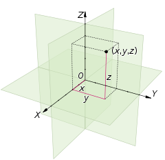
Cartesian Coordinates System
Geometric theory and polygons
Mesh modeling involves, effectivly a 3D space filled with join up coordinates on a grid to make polygons and edges. These coordinates are basic objects, points in the 3D space known as a vertex. Two of these vertices can hence be connected to form and edge, and another vertex makes another edge; forming the most basic polygon you can make; A triangle. This the very basic principle of how points in space can be connected mathmatically to form the most simple of shapes, but joined together, things can get much more complex resulting in vast and intricate 3D forms often make from thousands of vertices, edges and polygons. A well as trianglular polygons, if 4 vertices are connected rather than three, this will make a quad. A face refers to the polygons making up an element (a group of polygons with common vertices).
Mesh modeling involves, effectivly a 3D space filled with join up coordinates on a grid to make polygons and edges. These coordinates are basic objects, points in the 3D space known as a vertex. Two of these vertices can hence be connected to form and edge, and another vertex makes another edge; forming the most basic polygon you can make; A triangle. This the very basic principle of how points in space can be connected mathmatically to form the most simple of shapes, but joined together, things can get much more complex resulting in vast and intricate 3D forms often make from thousands of vertices, edges and polygons. A well as trianglular polygons, if 4 vertices are connected rather than three, this will make a quad. A face refers to the polygons making up an element (a group of polygons with common vertices).
According to Euclidean geometry, any group of three non-collinear points (points not lined up in a straight line) appoint a plane. It's obvious then, that a triangle must always inhabit a single plane as the three points are never lined up. It's difficult to say if this is true of more complex polygons due the more intricate workings of a 3D object. In a 2D object, the vertixes may only be lined up in one dimention, wheras in a 3D object, points could be alligned in any direction. A 3D object or vector that is flat and perpendicular to another object, is known as the normal. If the geometry is disrupted so will the normal be, and this can have a visiable effect as surface normals are often used for determining light transport in ray tracing.
The basic techniques explained here form the basic principles of 3D moddling. We know that vertices make edges, and edges form polygons.. But many polygons joined together make what is called a mesh, which, as a whole, is often referred to as a wireframe model. Such as the wireframe model of this dog below.
The basic techniques explained here form the basic principles of 3D moddling. We know that vertices make edges, and edges form polygons.. But many polygons joined together make what is called a mesh, which, as a whole, is often referred to as a wireframe model. Such as the wireframe model of this dog below.

It's easy to make mistakes in 3D moddeling, whether these be mathematical errors on the computers part of just a mistake gone unnoticed. These mistakes though can lead to intersecting polygons, which often are difficult to detect in wireframe view and are only realised once the surfaces have been applied and the model rendered. This can waste a lot of time as it means going back and correcting things, before having to re-render all over again. Moddlers need to be careful to ensure that mesh does not pierce itself, or contain errors such as double vertices, edges or faces, or be a manifold (A mesh containing holes and with missing polygons or singularities - a single vertex connection two distinct sections of a mesh). We can use the merge polygons tool to make sure there are no extra vertices, but it's very difficult to fix mistakes once they have been made so it's important to be thoughtful about this when creating models.
Primitives
Primitives
Primitives are pre-made objects intergrated into a 3D moddling software which allow the user to create that shape in a click. They're not particuarlly complex shapes, but having them on hand saves a lot of time and is a much much more efficient way of working. Usually, primitves come in simple shapes such as spheres or cubes, sometimes cyliners, pyramids, and even cones, but more often than not, the moddler simply takes elements of these shapes (Such as the roundered top of a sphere), and manipulates them to their needs. They are a shortcut, but it's not by any means cheating or doing the job for you, it's common practice in polygon moddling and saves a lot of hastle.

SurfacesSurfaces are texture effects and colour variants that can be applied to specific polygons or a set of polygons. Surfaces can either be chosen from the predefined presets of colours and textures or even have photographic maps added in order to acheive an even more realistic appearance. Sometimes a texture is commissioned and created for a particular object, in which case, the texture needs to wrap around the mesh, and needs to very precisely fit in all the right places. The example below shows the stages.

Information:
http://reference.wolfram.com/mathematica/guide/3DGeometryAndModelingFormats.html
http://en.wikipedia.org/wiki/3D_modeling
http://reference.wolfram.com/mathematica/guide/3DGeometryAndModelingFormats.html
http://en.wikipedia.org/wiki/3D_modeling
http://whatis.techtarget.com/definition/Cartesian-coordinates-rectangular-coordinates
http://www.basic-mathematics.com/cartesian-coordinate-system.html
http://en.wikipedia.org/wiki/Edge_(geometry)
http://en.wikipedia.org/wiki/Vertex_(geometry)
http://en.wikipedia.org/wiki/Polygonal_modeling
http://ultimate3d.org/Documentation/Primitive.htm
http://en.wikipedia.org/wiki/Geometric_primitive
http://3d.about.com/od/3d-101-The-Basics/a/Surfacing-101-Creating-A-UV-Layout.htm
No comments:
Post a Comment